33 Results
View results:
Sort by:
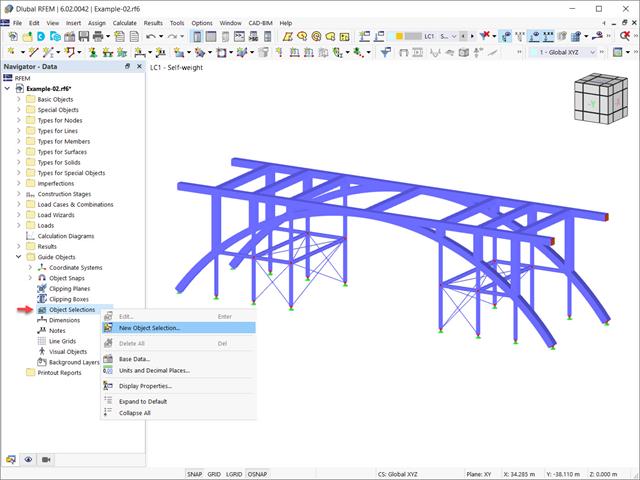
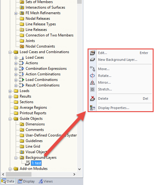
In the RFEM 6 and RSTAB 9 programs, it is possible to group objects based on different criteria. Hence, objects that meet the defined criteria can be selected and edited at the same time. This is possible with the “Object Selection” tool, which is comparable to “Special Selection” in RFEM 5. This article will show you how to group objects with “Object Selection" as a new guide object of RFEM 6 or RSTAB 9.

It is possible to edit a reinforcement layout or an existing reinforcement directly in the reinforcement's 3D rendering.

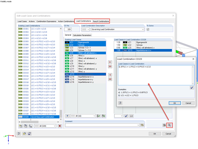
The dialog box for editing load or result combinations is a non-modal dialog box. This means that after you open this dialog box, you can edit the combinations outside the dialog box as well. For manually defining or editing a combination, a separate dialog box can be opened parallel to the "Edit load cases and combinations" dialog box.
RFEM and RSTAB offer the possibility to edit or check the combinations directly by entering text.
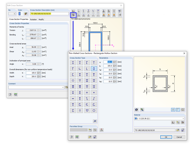
If you define a parametric cross-section in the library using its dimensions, the geometric properties are coded in the cross-section description; for example, "TO 200/100/10/10/10/10".
The printout report allows you to edit graphics subsequently.
In the Formula Editor environment, you can specify any parameters (lengths, force values, and so on) to control load and geometry data in the modeling.

In the "Edit Load Cases and Combinations" dialog box, you can combine different load cases in one load combination under the "Load Combinations" tab.

For a quick overview of the cross‑sections used, you can show the members in color sorted by cross‑section. Use the right mouse button in the work window to select "Colors in Graphics According to" → "Cross -Sections" from the shortcut menu. In the current program versions, you can use a panel with an editable color scale for this.
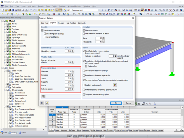
The transparency intensity of various graphic elements in the Solid Transparent Display Mode can be edited individually in the Program Options dialog box under the Graphic tab to improve the overview.
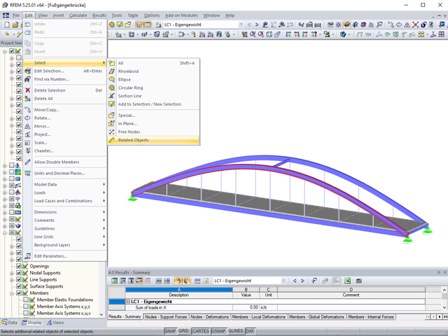
Sometimes it is necessary to add related objects, such as nodes and lines of a surface, to the selection in order to edit parts of the model.

RF-CONCRETE Members for RFEM or CONCRETE for RSTAB propose an automatically created reinforcement to the user if the "Design the provided reinforcement" option is selected in Window 1.6 "Reinforcement".
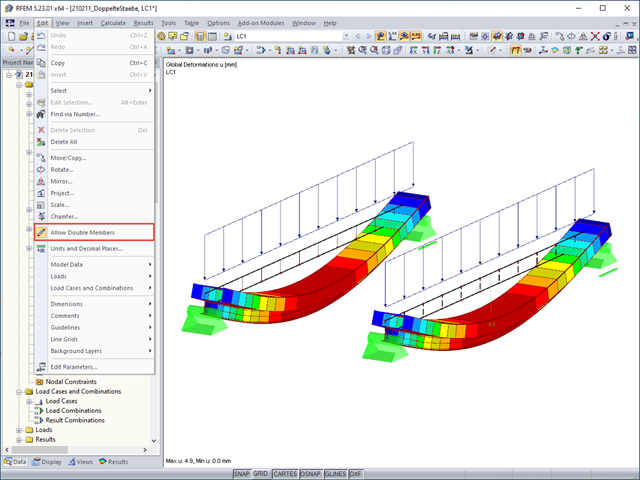
Generally, overlapping members in the model are not desired. To prevent RFEM from deleting an already defined member if another member is placed upon it, select "Allow Double Members" on the "Edit" menu.
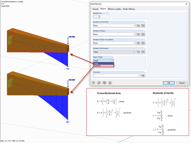
After right-clicking a member and selecting "Edit Member", you can find the "Taper Shape" option in the "Options" tab.
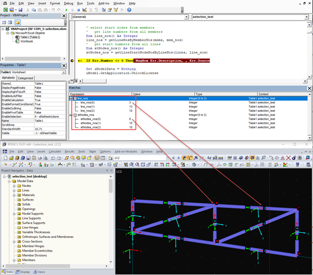
When editing elements via the COM interface, selecting elements is often a problem because it cannot be carried out visually via the work window. The selection can be particularly difficult for models that have been created via the program interface and are then to be modified using a separate program. Apart from the exception, when the selection was made previously via RFEM, there are several alternatives for programming.
.png?mw=640&hash=44d3f64925841d58547bef5a5e8ff90fab8aceaf)
The American Wood Council (AWC) has released the 2018 Edition of the National Design Specification (NDS) for Wood Construction. This is the second edition of the NDS to contain a chapter dedicated to cross-laminated timber (CLT) design. Therefore, a couple of revisions were included in the 2018 NDS when compared to the previous 2015 Edition.
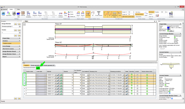
With program version RFEM 5.06, you can edit several tendons in the RF‑TENDON add‑on module simultaneously. To do this, it is necessary to select the corresponding tendons in the tendon arrangement table.
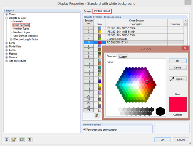
By clicking "Options" → "Display Properties" → "Edit", you can change and save display settings for printout reports and your screen. For example, you can set individual colors for cross‑sections.
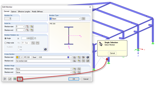
Member properties can be imported from the previously defined member in the "New Members" and "Edit Member" dialog boxes. To do this, click the [Select member and import its properties to the dialog box] button, then select the respective member.
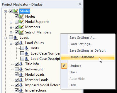
When you receive an RFEM or RSTAB file for further processing, the structures will be displayed in the program using the display settings of the last editor. If the settings do not correspond to your requirements, you can simply right‑click the empty area in Project Navigator - Display and select "Dlubal Standard". This returns the settings to the default values.
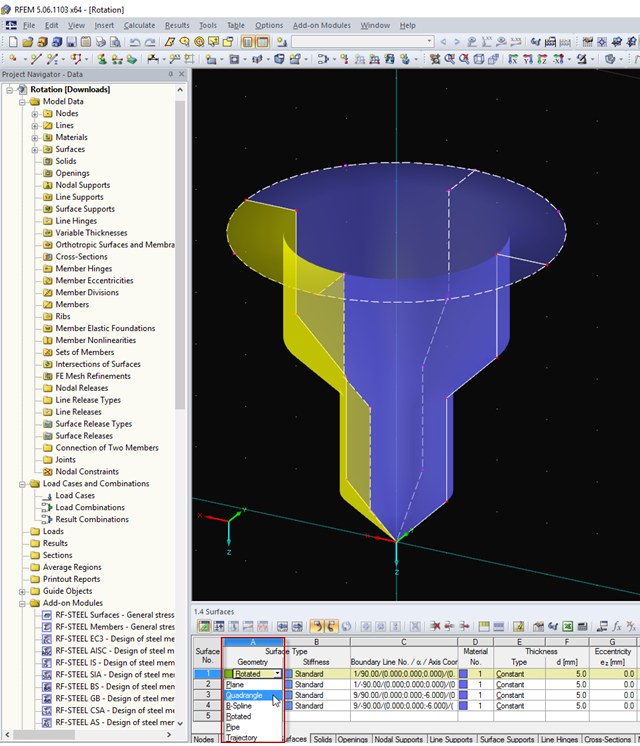
You can quickly model very complex objects in RFEM by rotating lines or polylines. If you need to change the model subsequently, quadrangle surfaces provide an advantage, as they include editable boundary lines.
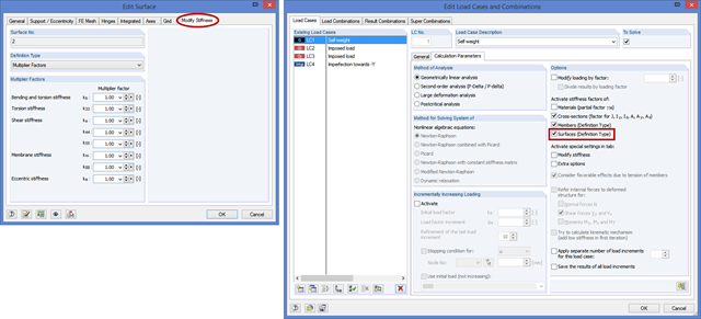
In the "Edit Surface" dialog box, there is a new tab titled "Modify Stiffness" for the "Standard" and "Without Tension" surface types. Here, you can modify the elements of a stiffness matrix by defining the factors in the same way as in the case of orthotropic surfaces.
DXF files can be imported as background layers in RFEM and RSTAB. They can have one to three dimensions. For this, you can use DXF files from other programs as well as DXF files exported from RFEM or RSTAB.
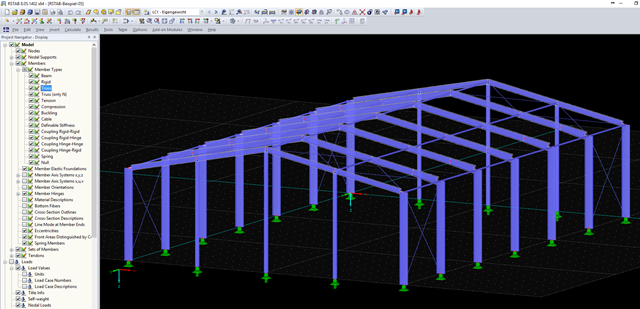
Users of RFEM and RSTAB already know the advantages of various visibilities that can be used to create user‑defined areas of the structure for further editing.
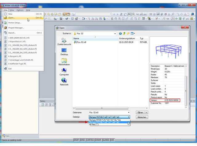
In RFEM, you can open and further edit structures with loads and load cases that have been modeled in RSTAB. For example, this may be necessary if you realize during the model input that it is useful to include surface elements such as wall surfaces and others in the existing RSTAB model.

The national parameters of EN 1992‑1‑1 for each country can be exported from RF‑/CONCRETE, RF‑/CONCRETE Columns, and RF‑/FOUNDATION Pro. To do this, there are interfaces with MS Excel, OpenOffice, and CSV. By exporting the national parameters, you can edit them in (for example) MS Excel, and display possible differences between the individual National Annexes clearly (see the image).
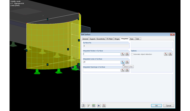
RFEM facilitates modeling by the automatic integration of objects into surfaces. However, it is impossible to integrate the objects automatically in the case of curved surfaces. For manual integration, select the relevant surfaces and click the "Edit Surfaces" option in the shortcut menu; then, in the "Integrated" tab, you can integrate the relevant objects using the "Select" function. This way, you can avoid error messages caused by non‑integrated objects when starting the calculation.
You can select an object in RFEM or RSTAB by simply clicking it. However, only the last object clicked will stay selected. In order to select several objects at a time, press the Control key while clicking. Since this procedure is not always possible, you can use the "Add to Selection" function in the toolbar or in the "Edit" → "Select" menu.
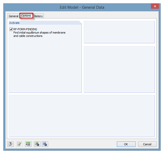
The RF‑FORM‑FINDING add‑on module can be activated in the "Edit Model - General Data" window, "Options" tab. By activating the module, a new RF‑FORM‑FINDING load case is created and an additional menu appears in the main program, allowing for the definition of prestress conditions for membrane and cable elements.
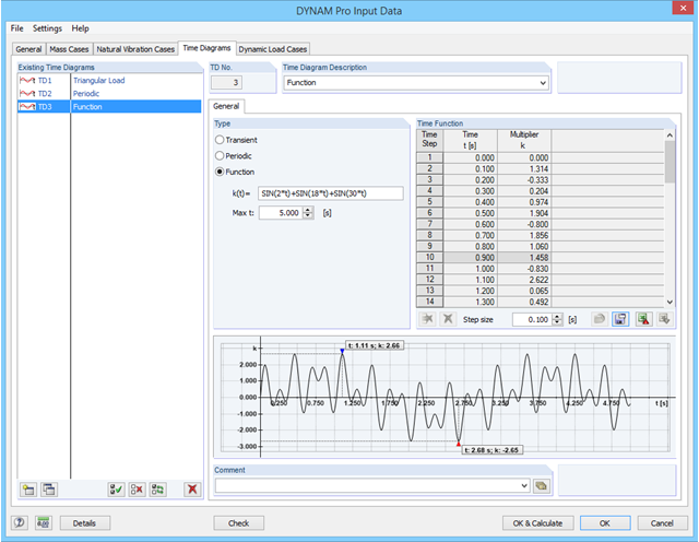
In RF-/DYNAM Pro - Forced Vibrations, you can define time diagrams directly as functions in an edit field. The parameter t is reserved for the time steps, but apart from that, all parameters as defined in the "Edit Parameter" dialog can be used in RF‑/DYNAM Pro.